OpenThread Temperature Sensor Network with Tock
This module and submodules will walk you through how to create a Tock temperature sensor network mote that communicates over a Thread network.
Hardware Notes
This tutorial requires a Tock-supported board that has an IEEE 802.15.4-compatible radio and supports Thread. While any such board should work, we recommend the nRF52840DK and assume this board is used throughout this tutorial.
Compatible boards:
- All Tock-supported boards with an
nRF52840chip, such as:
Project Setting
In this project we want to demonstrate how the Tock operating system can function as a flexible and reliable platform to build integrated systems. In particular, we demonstrate Tock's ability to run mutliple, mutually-distrustful applications on a single microcontroller, and it's IEEE 802.15.4 / Thread communications stack.
To demonstrate these features, we will build an HVAC control system for a shared office environment. Each employee will have access to their own HVAC control unit, connected to the central HVAC system through a Thread network. As the temperature set point can be a contencious subject, we allow each employee to enter their desired temperature. In turn, their control unit will display the average temperature set across all controllers, in addition to the current temperature at the control unit. We use Tock's OpenThread-based communications stack and its ability to run multiple concurrent applications to build this control unit (mote).
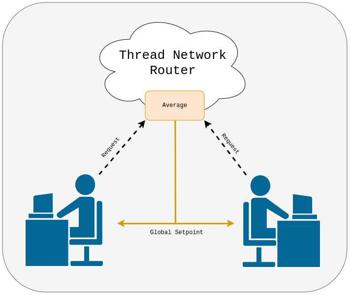
We divide the mote's functionality into three separate applications:
- The screen app drives the connected screen to display the current temperature and the local and global-average set points.
- The sensor app gathers readings from the
nRF52840's internal temperature sensor and exposes them to the control application. - Last but not least, the communication app is responsible for exchanging data with other participants using the Thread network.

By decoupling the sensor and communication applications, the Tock kernel ensures that the mote can remain responsive even in the case of failures in either application. In this tutorial we demonstratate this by injecting a bug into the communication application and deliberately faulting it with a malicious packet.
Software Prerequisites
- Getting Started Guide
- Rust
- Make
- GCC for ARM and RISC-V
- Tockloader Python Package
nRF52840dk Hardware Setup
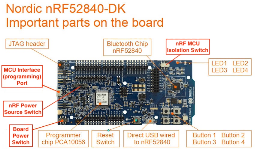
Make sure the switches and jumpers are properly configured on your board:
- The board "Power" switch on the bottom left should be set to "On".
- The "nRF power source" switch in the top middle of the board should be set to
"VDD".
- Note: If you have a screen already attached, this switch is partially hidden underneath the screen.
- The isolation switch, labeled "nRF ONLY | DEFAULT", on the top right should be set to "DEFAULT".
You should plug one USB cable into the side of the board for programming (NOT into the "nRF USB" port on the bottom right).
If you have a SSD1306-based screen with I2C pins, you should attach it to pins
P1.10 (SDA) and P1.11 (SCL).
See this diagram for the full configuration:
     ┌────────────────┬───┬─────────────────┐
     │┌POWER┐         │USB│← PROG/DEBUG     │
     ││ ON ▓│         └───┘                 │
     ││OFF ░│                               │
     │└─────┘          ┌──DEBUG──┐          │
     │                 │VDD nRF ▪│  P0.27 □ │
     │                 │VDD nRF ▪│  P0.26 □ │
     │ □ VDD   ┌SOURCE┐│SWD SEL ▪│  P0.02 □ │
     │ □ VDD   │LiPo ░││ SWD IO ▪│    GND □ │
     │ □ RESET │ VDD ▓││SWD CLK ▪│  P1.15 □ │
VCC →│ ▣ VDD   │ USB ░││    SWO ▪│  P1.14 □ │
     │ □ 5V    └──────┘│  RESET ▪│  P1.13 □ │
     │ □ GND           │        ▪│  P1.12 □ │
GND →│ ▣ GND     ┌────┐│    VIN ▪│  P1.11 ▣ │← I2C SCL
     │ □ NC      │JTAG││  VDDHV ▪│  P1.10 ▣ │← I2C SDA
     │         ┐ │    ││  VDDHV ▪│          │
     │ □ P0.03 │ └────┘│ VIOREF ▪│  P1.08 □ │
     │ □ P0.04 A       │        ▪│  P1.07 □ │
     │ □ P0.28 D       └─────────┘  P1.06 □ │
     │ □ P0.29 C                    P1.05 □ │
     │ □ P0.30 │                    P1.04 □ │
     │ □ P0.31 │                    P1.03 □ │
     │         ┘                    P1.02 □ │
     │                              P1.01 □ │
     │                                      │
     │                              P0.10 □ │
     │                              P0.09 □ │
     │                              P0.08 □ │
     │ ☉ RESET                      P0.07 □ │
     │   BTN                        P0.06 □ │
     ├───┐                          P0.05 □ │
     │USB│  nRF                     P0.01 □ │
     │   │← PERIPHERAL              P0.00 □ │
     ├───┘                           ┌─────┐│
     │                               │░ nRF││
     │BTN3 BTN1                      │▓ DEF││
     │ ☉    ☉                        └─────┘│
     │BTN4 BTN2                  LED3 LED1  │
     │ ☉    ☉                     □    □    │
     │                ┌───┐      LED4 LED2  │
     │ ┌─┐            │nRF│       □    □    │
     │ │ │NFC         └───┘                 │
     │ └─┘                                  │
     └───                    ───────────────┘
         ╲                  ╱
          ──────────────────
Organization and Getting Oriented to Tock
Tock consists of multiple inter-working components. We briefly describe the general structure of Tock and will deep-dive into these components throughout the tutorial:
A Tock system contains primarily two components:
- The Tock kernel, which runs as the operating system on the board. This is compiled from the Tock repository.
- Userspace applications, which run as processes and are compiled and loaded separately from the kernel.
The Tock kernel is compiled specifically for a particular hardware device,
termed a "board". Tock provides a set of reference board files under
/boards/<board name>. Any
time you need to compile the kernel or edit the board file, you will go to that
folder. You also install the kernel on the hardware board from that directory.
While the Tock kernel is written entirely in Rust, it supports userspace applications written in multiple languages. In particular, we provide two userspace libraries for application development in C and Rust respectively:
libtock-cfor C applications ( tock/libtock-c )libtock-rsfor Rust applications ( tock/libtock-rs )
We will use libtock-c in this tutorial. Its example applications are located
in the /examples
directory of the libtock-c repository.
Thread Router
For this tutorial, we assume that one nRF52840DK is dedicated to be a Thread router board. As a participant in a hosted tutorial, you will likely not need to set this up yourself. However, we do provide a pre-built image and some instructions for how to set up this router as well.
Stages
We divide this tutorial into five stages, with checkpoints that you can use to skip ahead. Each stage contains information on how to obtain all checkpoint-code required for it.
-
Sensor Application: We start by creating a simple application that reads the
nRF52840DKinternal temperature sensor and prints the current temperature onto the console.This demonstrates how you can flash a Tock kernel and applications onto your development board, and introduces some key Tock concepts.
-
Following this, we develop the communication application. This application will let our mote join the Thread network.
-
We continue by adding the screen application. This app will:
- Receive user input to set the desired temperature.
- Display the measured temperature, desired temperature setpoint, and global setpoint to the attached OLED screen.
-
Taking these three applications, we then add IPC functionality to allow for passing data between applications.
-
Finally, we demonstrate how Tock's mutually distrustful application model can protect the system from misbehavior in any given app.
Sound good? Let's get started.